


Introduction: The Most Successful Invisible Technology of the Last Twenty Years
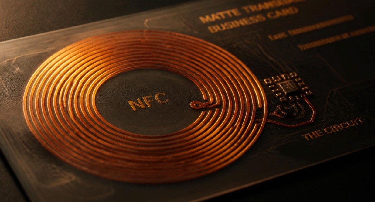
There is a good chance you used Near Field Communication at least three times today. You tapped a card against a terminal to buy coffee. You held your phone to a barrier at a train station. You touched a hotel key card to a door and heard the lock click. Perhaps you tapped a a tappable card like this one against someone’s phone and watched a contact page appear on their screen a half-second later.
None of those interactions required you to think about radio frequencies, inductive coupling, load modulation, or byte-level data structures. That is precisely the point. NFC is one of the rare technologies that succeeded by becoming completely invisible. It works, it works quickly, and almost nobody who uses it every day has any idea what is actually happening in that four-centimetre gap between the two objects.
This guide is for the people who want to know anyway.
What follows is not a marketing overview. It is a technical explanation of how NFC actually functions at the physical layer, the protocol layer, and the data layer — written for engineers, product managers, procurement teams, and anyone who has to make a decision about NFC hardware and would rather make it from a position of understanding.
By the end you will understand:
- Why 13.56 MHz was chosen and what that frequency physically does
- How a passive tag with no battery draws power out of thin air
- What “load modulation” means and why it is the clever bit
- The difference between ISO/IEC 14443, ISO/IEC 18092, and the NFC Forum tag types
- What actually sits in the memory of an NTAG213, NTAG215 or NTAG216, byte for byte
- How an NDEF record is structured and why record type matters
- Why some tags work at 4 cm and others struggle at 1 cm
- How to specify, source and validate NFC hardware without getting burned
We will move from physics upward. If you only want the practical procurement advice, jump to Section 12 — but the earlier sections are what let you tell a good supplier from a bad one.
1. A Short History: Where NFC Came From
NFC did not appear from nothing. It is the direct descendant of RFID — Radio Frequency Identification — a family of technologies with roots stretching back to the Second World War, when Allied aircraft carried transponders that responded to radar interrogation with an identifying signal. That basic pattern — a reader emits energy, a transponder responds with an identity — is unchanged seventy years later.
Commercial RFID matured through the 1970s and 1980s across a spread of frequency bands. Low-frequency systems at 125–134 kHz became the standard for animal tagging and simple access control: short range, slow, but tolerant of water and metal. Ultra-high-frequency systems at 860–960 MHz became the backbone of supply-chain logistics, readable at several metres, which is exactly what you want when a pallet passes through a warehouse door.
In the middle sat the high-frequency band at 13.56 MHz. It offered a useful compromise: enough range to be convenient, short enough to be deliberate, and enough bandwidth to move real data rather than just an identifier. Two standards crystallised around it. ISO/IEC 14443, published in the late 1990s, defined proximity integrated circuit cards — the technology behind contactless bank cards and transit passes. ISO/IEC 15693 defined vicinity cards, with slightly longer range and lower data rates.
The pivotal moment came in March 2004, when Nokia, Philips Semiconductors (which later became NXP Semiconductors), and Sony founded the NFC Forum. Their stated purpose was to harmonise and build on existing RFID standards to create a coherent, interoperable Near Field Communication ecosystem. Membership passed one hundred organisations by December 2006. Today the Forum’s sponsor-level members read like a roll call of the entire consumer electronics and payments industry: Apple, Google, Samsung, Qualcomm, Sony, Infineon, NXP, STMicroelectronics, Mastercard and Visa among them.
The Forum’s output over the following two decades built the layer that made NFC usable rather than merely possible:
- June 2006 — The NFC technology architecture and first five specifications are published.
- July 2007 — Four tag type specifications are issued, defining how different chips should behave.
- December 2010 — The certification programme launches, and the fifteenth specification is published.
- October 2012 — The NFC Analog technical specification is published, standardising RF behaviour.
- November 2012 — The NFC Controller Interface (NCI) specification arrives, defining how a host processor talks to an NFC chip.
- October 2015 — The Type 5 Tag specification extends the family to ISO/IEC 15693 devices.
- January 2019 — A specification for wireless charging of IoT devices over NFC is announced.
Meanwhile the underlying protocol standard, ECMA-340 (mirrored as ISO/IEC 18092 and known as NFCIP-1), continued to evolve. Its fourth edition, published in June 2024, aligns with the third edition of ISO/IEC 18092:2023 and introduces a security standard for the Target device alongside harmonisation with the NFC Forum’s own Digital Protocol and Activity specifications.
The commercial inflection point, though, was not a specification. It was Apple adding NFC to the iPhone 6 in 2014 for Apple Pay, and then — critically — opening background tag reading in iOS 13 in 2019. Before that, an iPhone user had to open a dedicated app to read an NFC tag. After it, an iPhone simply detected a tag when unlocked and offered to act on it. That single change is what made NFC viable for consumer-facing applications like smart posters, product authentication, and contactless business cards. Android had supported this since 2011; the moment iOS matched it, the addressable audience roughly doubled overnight.
2. Why 13.56 MHz? The Physics of Frequency Choice
Every wireless technology involves a trade-off between range, data rate, power consumption, antenna size, and interference. Frequency is the single biggest lever on all of them.
13.56 MHz sits in the high-frequency portion of the radio spectrum, with a wavelength of approximately 22 metres. That number matters enormously, and it is where most casual explanations of NFC go wrong.
2.1 Near field versus far field
Radio communication generally happens in the far field — the region beyond roughly one wavelength from the antenna, where the electric and magnetic components of the wave have detached from the antenna and propagate outward as a self-sustaining electromagnetic wave. Wi-Fi, mobile data, and Bluetooth all work this way.
NFC does not. At 13.56 MHz with a 22-metre wavelength, any device operating within a few centimetres is deep inside the near field — specifically the reactive near field, the region within roughly λ/2π (about 3.5 metres) where the magnetic field dominates and energy is still bound to the antenna rather than radiating away.
This is why NFC is properly described as magnetic inductive coupling, not radio transmission. The reader and the tag behave less like a transmitter and a receiver and more like the primary and secondary windings of a loosely coupled air-core transformer. Energy is not broadcast; it is shared through a shared magnetic field.
The practical consequences are enormous, and they are the reason NFC won:
Range falls off catastrophically with distance. In the far field, signal strength decays with the inverse square of distance. In the reactive near field, magnetic field strength decays with roughly the inverse cube. Double the distance and you get one-eighth the coupling. This is not a bug — it is the security model. An NFC interaction is physically constrained to a few centimetres, which makes remote interception genuinely difficult rather than merely discouraged.
Physical proximity implies intent. Because you must bring two objects within about four centimetres of each other, an NFC interaction cannot happen by accident in the way a Bluetooth pairing prompt can. The gesture is the consent.
Antennas can be small and flat. A resonant antenna at 13.56 MHz would need to be metres long — impossible in a card. But near-field coupling does not require a resonant-length antenna; it requires a loop of sufficient area. A few turns of etched copper or printed silver around the perimeter of a card produces enough loop area to couple effectively, which is why an NFC inlay can be thinner than a sheet of paper.
The band is globally licence-free. 13.56 MHz sits in an ISM (Industrial, Scientific and Medical) band available worldwide without a licence. A card manufactured in Shenzhen works against a reader in Manchester, São Paulo, or Tokyo. No regional variants, no regulatory approval per market.
2.2 Why not the alternatives?
Low frequency at 125 kHz offers excellent penetration through water and reasonable tolerance of nearby metal, but data rates are glacial and memory capacity is minimal. It is fine for an access fob that transmits a fixed number; it is useless for storing a URL, let alone a payment credential.
Ultra-high frequency at 900 MHz reads at several metres, which sounds superior until you consider the application. A business card that could be read from across a room is a privacy problem, not a feature. UHF also behaves badly near the human body — water absorbs those frequencies efficiently, and a card in a wallet in a pocket is surrounded by water.
2.4 GHz — the Bluetooth and Wi-Fi band — requires active power on both ends. There is no such thing as a passive, battery-free 2.4 GHz tag that can be read from a phone. That single constraint rules it out for anything embedded in a card.
13.56 MHz is the only band where you can have all of: passive operation, sub-second interaction, a few kilobits of data, a card-sized antenna, global licence-free operation, and a range short enough to be a security feature.
3. How a Passive Tag Powers Itself
The most counter-intuitive thing about an NFC tag is that it contains no battery, no capacitor charged at the factory, and no power source of any kind — yet it runs a microcontroller, performs cryptographic operations, writes to non-volatile memory, and transmits data.
All of that energy arrives from the reader in the moment of the tap.
3.1 The reader side
An NFC reader — the chip in a phone, a payment terminal, or a USB reader — drives an oscillating current through its antenna coil at 13.56 MHz. That alternating current generates an oscillating magnetic field around the coil. Regulatory limits cap the field strength, typically expressed as H-field in amperes per metre; NFC Forum and ISO specifications define a minimum operating field (H_min) that a compliant reader must produce and a maximum (H_max) it must not exceed.
The reader’s antenna is part of a tuned resonant circuit — an LC tank deliberately tuned so that its resonant frequency sits at or very near 13.56 MHz. Resonance is what makes the whole thing efficient: at resonance, a modest drive current produces a much larger circulating current in the coil, and therefore a much stronger magnetic field.
3.2 The tag side
The tag contains its own coil — typically three to six turns of etched aluminium or copper, or printed conductive ink, around the perimeter of the inlay — connected to a tuning capacitor, which is usually integrated onto the chip die itself. Together they form a second resonant circuit, also tuned to 13.56 MHz.
When the tag’s coil enters the reader’s oscillating magnetic field, Faraday’s law of induction takes over: a changing magnetic flux through a conductive loop induces an electromotive force around that loop. An alternating voltage appears across the tag’s coil.
That AC voltage is fed into a rectifier on the chip — typically a full-wave bridge of diodes or diode-connected transistors — which converts it to DC. A shunt regulator clamps the resulting supply rail to a safe level (NTAG-class chips regulate to around 1.8 V for internal logic), dumping excess energy as heat when the tag is very close to the reader and coupling is strong. A small on-die capacitor smooths the rail.
Within a millisecond or two of entering the field, the chip has a stable supply and boots.
The power budget is genuinely tiny — typically tens of microwatts to a few milliwatts depending on coupling. This is why NFC tag chips are so architecturally constrained. There is no room for a general-purpose CPU. What you get instead is a hard-wired state machine: an RF interface, an anti-collision unit, a command interpreter, a digital control unit, and an EEPROM interface. NXP’s own block diagram of the NTAG21x family shows exactly these blocks and nothing more.
The single most power-hungry operation is writing to EEPROM. Flipping a bit in non-volatile memory requires a charge pump to generate a voltage higher than the supply rail, and it takes milliseconds rather than microseconds. This is why a write operation demands closer proximity and a steadier hand than a read, and why “tearing” — pulling the tag out of the field mid-write — is a real failure mode that good chips explicitly protect against.
4. Load Modulation: How the Tag Talks Back
Powering the tag is the easy half. The harder question is how a device with no transmitter sends data back to the reader.
The answer is load modulation, and it is genuinely elegant.
4.1 The principle
The reader and tag coils are magnetically coupled. That coupling is bidirectional: not only does the reader’s field induce a current in the tag, but any change in the tag’s current draw reflects back and alters the impedance the reader’s own antenna presents to its driver circuit.
Put simply: when the tag draws more power, the reader’s antenna gets slightly harder to drive.
The tag exploits this deliberately. It has a switchable load — usually a resistor or capacitor that can be connected across its coil by a transistor. Switching that load on and off changes the reflected impedance, which produces a small but measurable amplitude variation in the voltage across the reader’s antenna. The tag is not generating a signal; it is modulating the reader’s own signal by varying how much energy it absorbs.
The variation is tiny — often well under one percent of the carrier amplitude. Detecting it directly against a carrier that is many orders of magnitude larger would be extremely difficult.
4.2 Subcarriers
The solution is a subcarrier. Rather than switching the load at the data rate, the tag switches it at 847.5 kHz — exactly the carrier frequency divided by 16 (13.56 MHz / 16 = 847.5 kHz). The data then modulates that subcarrier.
This moves the tag’s response into sidebands sitting 847.5 kHz above and below the 13.56 MHz carrier. The reader can now filter out the enormous carrier and look only at those sidebands, where its own transmission contributes nothing. A signal that was hopeless to detect at baseband becomes straightforward.
The frequency division by 16 is not arbitrary. Both devices derive all timing from the same 13.56 MHz carrier, so they are inherently synchronised. The tag has no crystal oscillator — it cannot afford one — so every clock it uses is a divided-down version of the field it is sitting in. This is why the carrier is often written as fc in the standards, with data rates expressed as fc/128, fc/64 and fc/32.
4.3 Data rates and coding
Those divisions give the three standard bit rates defined in ECMA-340: fc/128 = 106 kbit/s, fc/64 = 212 kbit/s, and fc/32 = 424 kbit/s. Most passive tags used in cards and stickers operate at 106 kbit/s.
Reader-to-tag communication in the Type A scheme uses modified Miller coding with 100 percent amplitude shift keying — the reader briefly switches its field off entirely to signal a bit. The pauses are short (a few microseconds) and the tag’s on-chip capacitor carries it through the gap without losing power.
Tag-to-reader communication uses Manchester coding on the 847.5 kHz subcarrier. Manchester coding guarantees a transition in the middle of every bit period, which makes clock recovery robust and makes the average DC level constant regardless of the data — both valuable properties when your signal is a tiny amplitude wobble.
Every frame is protected by a CRC. ECMA-340 specifies CRC calculation for both fc/128 and the higher rates, with worked examples in its normative Annex A. A frame that fails CRC is discarded and, in practice, the reader simply retries — which happens fast enough that the user never perceives it.
5. Anti-Collision: What Happens When There Are Two Tags
Bring two NFC tags into the same field and both will power up and both will try to respond. Without a mechanism to sort this out, the reader receives two overlapping responses and understands neither.
The solution is anti-collision, sometimes called Single Device Detection (SDD) in the NFCIP-1 standard.
The Type A scheme uses a bitwise binary search over the tag’s unique identifier (UID). The process runs roughly as follows:
- The reader sends a REQA (Request Type A) command. Every tag in the field responds with ATQA (Answer to Request), a short frame indicating its UID size and capabilities. If two tags respond simultaneously, the frames collide.
- The reader issues an anti-collision command specifying a UID prefix of length zero — effectively “everyone respond with your UID.”
- Tags respond with their UIDs. Where two tags have different bits at the same position, the reader detects a collision — with Manchester coding, a collision at a given bit position produces a distinctive signal that is neither a clean one nor a clean zero, so the reader knows exactly which bit position failed.
- The reader then re-issues the command with a longer prefix, arbitrarily selecting one branch of the tree — “only tags whose UID starts with these bits should respond.”
- This repeats, extending the prefix one bit at a time, until exactly one tag matches.
- The reader sends SELECT with that full UID. That tag enters the ACTIVE state; all others go quiet.
Once the reader is finished with that tag, it can issue a HALT and repeat the process to enumerate the next one.
UIDs come in three sizes: single (4 bytes), double (7 bytes), and triple (10 bytes). NTAG-class chips use a 7-byte UID, which is programmed at the factory into the first pages of memory and permanently locked. This matters for authentication use cases: the UID cannot be rewritten on a genuine NXP chip, so reading it and checking it against a database is a meaningful — though not cryptographically strong — integrity check.
A practical note that trips up a lot of deployments: the anti-collision procedure is fast, but it is not instantaneous, and it assumes both tags are properly powered. Two cards stacked in a wallet frequently produce a worse outcome than a clean collision — they detune each other’s resonant circuits, so neither couples properly and the reader sees nothing at all. This is why payment terminals often display “present one card only,” and why an NFC business card should be presented alone rather than through a stack of other cards.
6. The Standards Landscape, Untangled
The standards around NFC are genuinely confusing because several bodies standardised overlapping things at different times. Here is the map.
6.1 ISO/IEC 14443 — Proximity cards
The foundational standard for 13.56 MHz proximity cards, published in four parts:
- Part 1 — Physical characteristics (card dimensions, durability requirements)
- Part 2 — RF power and signal interface, defining Type A and Type B modulation schemes
- Part 3 — Initialisation and anti-collision
- Part 4 — Transmission protocol (a higher-level, block-oriented protocol used by smart cards)
Type A and Type B differ in their modulation and coding. Type A uses 100 percent ASK with modified Miller from reader to card; Type B uses 10 percent ASK with NRZ coding. Both are widely deployed. NTAG chips and most consumer NFC tags are Type A. Many national ID cards and some payment cards are Type B.
Nominal operating range for ISO 14443 is defined as up to about 10 cm, though real-world performance in a small-antenna device like a phone is typically 1–4 cm.
6.2 ISO/IEC 15693 — Vicinity cards
A separate standard, also at 13.56 MHz, designed for longer range — up to around a metre with a large reader antenna. It uses different modulation and a different command set. Library book tags and some industrial applications use it. The NFC Forum brought it into the fold as Type 5 in October 2015.
6.3 ISO/IEC 18092 / ECMA-340 — NFCIP-1
This is the standard that defines NFC as distinct from plain RFID. Its key contribution is peer-to-peer communication: two active devices that can each generate their own field and take turns being initiator and target. It defines both passive communication mode (one device powers the other, as with a tag) and active communication mode (both devices generate their own field alternately).
NFCIP-1 defines the three bit rates, the initialisation and anti-collision procedures for each, the transport protocol with its Attribute Request/Response, Wakeup, and Parameter Selection commands, the Data Exchange Protocol including chaining for messages that exceed a single frame, and clean deactivation via Deselect and Release commands.
The 2023/2024 revisions added a security standard for the Target and harmonised the document with the NFC Forum’s Digital Protocol and Activity specifications — an important step, because for years implementers had to reconcile two overlapping descriptions of the same behaviour.
6.4 NFC Forum Tag Types
Sitting above the ISO standards, the NFC Forum defined tag types — behavioural profiles that guarantee a compliant reader knows how to interact with a compliant tag.
| Type | Underlying standard | Typical chips | Memory | Notes |
| Type 1 | ISO 14443A | Topaz / Jewel | 96 bytes – 2 KB | Largely obsolete |
| Type 2 | ISO 14443A | NTAG21x, MIFARE Ultralight | 48 bytes – 888 bytes | The workhorse of consumer NFC |
| Type 3 | JIS X 6319-4 (FeliCa) | Sony FeliCa | Variable, up to 1 MB | Dominant in Japan |
| Type 4 | ISO 14443A/B | DESFire, SmartMX | 4 KB – 32 KB+ | Full smart card, supports strong crypto |
| Type 5 | ISO 15693 | ICODE SLIX, ST25TV | 256 bytes – 2 KB | Longer range, added 2015 |
For the overwhelming majority of applications — smart posters, product tags, contactless business cards, marketing collateral — Type 2 is the correct answer, and in practice that means an NTAG21x chip.
7. Inside an NTAG Chip: The Byte-Level Reality
NXP’s NTAG213, NTAG215 and NTAG216 are the de facto standard for consumer NFC tags. They were developed as standard NFC tag ICs for mass-market applications in retail, gaming and consumer electronics, and they comply fully with the NFC Forum Type 2 Tag specification. If you buy an NFC sticker, an NFC business card, or an NFC-enabled product tag, there is a strong chance one of these three chips is inside it — and knowing which one, and what it actually contains, is the difference between a specification you can trust and a number on a marketing page.
7.1 Total memory versus user memory
This is the single most common source of confusion, and the place where a lot of low-quality suppliers quietly mislead buyers.
Every NTAG chip has three different “memory” numbers, and they are not interchangeable:
| Chip | Total EEPROM | Pages | User memory (read/write) | NDEF message capacity |
| NTAG213 | 180 bytes | 45 pages × 4 bytes | 144 bytes | 132 bytes |
| NTAG215 | 540 bytes | 135 pages × 4 bytes | 504 bytes | 492 bytes |
| NTAG216 | 924 bytes | 231 pages × 4 bytes | 888 bytes | 872 bytes |
The total EEPROM figure includes the UID, the capability container, lock bytes, configuration pages and the one-time-programmable area. The user memory figure is what you can actually write to. The NDEF capacity figure is smaller still, because an NDEF message needs its own TLV wrapper and record headers before your payload begins.
The memory map is organised in 4-byte pages. On an NTAG213, pages 04h to 81h are the user read/write area. On NTAG215 it is 04h to 81h in the same pattern extended, and on NTAG216 it runs to E1h. Above the user area sit the dynamic lock bytes, then the configuration pages — 83h to 86h on NTAG215, E3h to E6h on NTAG216 — which control memory access restriction and the UID ASCII mirror feature.
The capability container at page 3 encodes the tag’s data area size. Its third byte reads 12h on NTAG213 (encoding 144 bytes), 3Eh on NTAG215 (496 bytes) and 6Dh on NTAG216 (872 bytes). Writing to the CC is effectively one-way: once you set the read-only bits, they stay set.
7.2 What this means practically
A plain URL of 30 characters fits comfortably on an NTAG213. A vCard with a name, job title, company, phone number, email address and a website will typically run 200–400 bytes and will not fit on an NTAG213 — you need at least an NTAG215.
This is the technical reason that well-designed contactless business cards store a short URL rather than a full vCard. Writing https://evry.cd/a7f3k to the tag consumes around 25 bytes, fits on any chip, loads a rich profile page that can be updated at any time without re-encoding the card, and can be analytically tracked. Writing a raw vCard consumes most of the chip, cannot be changed after the card is printed, and gives you no data. It is a good example of a case where the constrained approach is also the better product decision — and it is why serious cards built by Evrycard resolve to a hosted profile rather than dumping a static contact file onto the chip.
7.3 Security features on NTAG21x
Despite being cheap Type 2 tags, the NTAG21x family includes a meaningful set of protections:
Password protection. A 32-bit password (PWD) and a 16-bit password acknowledge (PACK) can be configured to protect a specified range of pages from writing, or optionally from reading as well. The protection start page is configurable — per 4 pages on NTAG213, per 16 pages on NTAG215 and NTAG216. Importantly, this is not strong cryptography: the password is transmitted in the clear over the RF interface. It defends against casual overwriting by someone with a phone, not against a determined attacker with a sniffer.
Authentication attempt limiting. The configuration allows an optional limit on unsuccessful password attempts, after which the tag refuses further attempts. This meaningfully raises the cost of brute-forcing a 32-bit password.
Lock bytes. Static and dynamic lock bytes let you permanently set individual pages or blocks of pages to read-only. Once locked, that is irreversible — there is no unlock command. This is the correct mechanism for a card you never intend to reprogram.
Anti-tearing support. The chip provides anti-tearing protection for the capability container and lock bytes, meaning that if the tag leaves the field mid-write to those critical structures, it will not be left in a corrupt half-written state. This is a real and valuable feature; a corrupted CC can render a tag permanently unreadable.
UID ASCII mirror. The configuration pages can enable automatic mirroring of the 7-byte UID as ASCII text into the NDEF message. This means a tag can serve a URL like https://example.com/verify?uid=04A1B2C3D4E5F6 where the UID portion is inserted by the chip itself at read time, without being writable. Combined with a server-side check, it provides a lightweight anti-cloning signal — the URL cannot be copied onto a different chip and still carry the right UID.
NFC counter. NTAG213 and above can maintain a one-way read counter that increments on each read and can also be mirrored into the NDEF message. This lets a server detect replay: if a URL arrives with a counter value lower than one already seen, something is wrong.
For applications requiring genuine cryptographic security — payment, access control, high-value authentication — none of this is sufficient, and you need a Type 4 device such as MIFARE DESFire EV3, which supports AES-128 mutual authentication and encrypted, MAC-protected communication. But for the vast majority of tag applications, NTAG21x with a locked CC and a password-protected user area is proportionate.
8. NDEF: The Data Format That Makes It Interoperable
A chip with 504 bytes of writable memory is useless unless every reader in the world agrees on how to interpret those bytes. That agreement is NDEF — the NFC Data Exchange Format.
8.1 Structure
An NDEF message is a container holding one or more NDEF records. Each record has a header followed by a payload.
The header’s first byte carries a set of flags:
- MB (Message Begin) — set on the first record of a message
- ME (Message End) — set on the last record
- CF (Chunk Flag) — indicates this record is part of a chunked payload
- SR (Short Record) — set when the payload is under 256 bytes, allowing a 1-byte length field instead of 4
- IL (ID Length present) — indicates an optional ID field follows
- TNF (Type Name Format) — a 3-bit field identifying how to interpret the type
TNF values are the branch point for everything that follows:
| TNF | Meaning |
| 0x00 | Empty |
| 0x01 | NFC Forum Well-Known Type |
| 0x02 | MIME media type (RFC 2046) |
| 0x03 | Absolute URI (RFC 3986) |
| 0x04 | NFC Forum External Type |
| 0x05 | Unknown |
| 0x06 | Unchanged (used in chunking) |
8.2 The record types that matter
URI records (TNF 0x01, type “U”) are the most important record type in practice. They store a URL — and they do it with a clever compression trick. The first byte of the payload is a prefix code that stands in for a common URL prefix:
| Code | Prefix |
| 0x00 | (none) |
| 0x01 | http://www. |
| 0x02 | https://www. |
| 0x03 | http:// |
| 0x04 | https:// |
| 0x05 | tel: |
| 0x06 | mailto: |
Using prefix 0x04 for an HTTPS URL saves seven bytes. On an NTAG213 with 132 usable NDEF bytes, seven bytes is over five percent of your budget. Suppliers whose encoding tooling does not use prefix codes are quietly wasting your memory.
Text records (TNF 0x01, type “T”) store plain text with a language code. Useful, but note that a text record on its own does nothing on a phone — iOS and Android will display it but take no action. If you want a tap to do something, you need a URI record.
MIME records (TNF 0x02) carry arbitrary typed data. A vCard is stored as a MIME record with type text/vcard. Android handles these natively and will offer to add the contact. iOS is far less consistent.
External records (TNF 0x04) use a namespaced type like android.com:pkg, used to trigger a specific app. The Android Application Record (AAR) is the classic example: append one to your message and Android will open that specific app, or take the user to the Play Store if it is not installed.
Smart Poster records are compound records that wrap a URI together with a title, an action, and optionally an icon and size hints. Conceptually elegant; in practice support is patchy and most implementations simply use a bare URI record instead.
8.3 The TLV wrapper
On a Type 2 tag, the NDEF message does not sit raw in memory. It is wrapped in a TLV (Tag-Length-Value) structure:
- T — one byte identifying the block type (0x03 for an NDEF message, 0x00 for NULL padding, 0xFE for terminator)
- L — the length, either one byte for lengths under 255 or three bytes for longer
- V — the NDEF message itself
A terminator TLV (0xFE) marks the end of valid data. This overhead is why an NTAG213’s 144 bytes of user memory yields only 132 bytes of NDEF capacity.
8.4 Worked example
Encoding https://evry.cd/a7f3k onto a tag:
“`
Byte 0: 03 TLV type: NDEF message
Byte 1: 10 TLV length: 16 bytes
Byte 2: D1 Header: MB=1, ME=1, SR=1, TNF=001
Byte 3: 01 Type length: 1
Byte 4: 0C Payload length: 12
Byte 5: 55 Type: ‘U’ (URI)
Byte 6: 04 Prefix: https://
Bytes 7-17: 65 76 72 79 2E 63 64 2F 61 37 66 33 6B
“evry.cd/a7f3k”
Byte 18: FE Terminator TLV
“`
Nineteen bytes total for a fully functional tap-to-open-profile tag. That fits on the smallest chip with room to spare — which is the whole argument for the short-URL approach.
9. Antenna Design: Why Some Tags Just Work Better
Two tags with identical NTAG216 chips can perform completely differently. The chip is rarely the variable. The antenna almost always is.
9.1 Loop area is king
Coupling strength depends on how much magnetic flux passes through the tag’s coil, which depends directly on the enclosed area of the loop. A full credit-card-sized antenna (roughly 80 × 45 mm of usable loop) will read at three to four centimetres from a typical phone. A 25 mm circular sticker antenna might manage one centimetre against the same phone.
This is why full card-format tags outperform small stickers or keyfobs so noticeably, and it is worth understanding before you evaluate samples: if you test a small-format tag and a card-format tag side by side, you are testing antenna geometry, not chip quality.
9.2 Tuning and detuning
The tag’s coil plus its tuning capacitor form a resonant circuit that should peak at or slightly above 13.56 MHz. Manufacturers typically tune slightly high — around 13.8–14.5 MHz — because real-world conditions (a phone’s own metalwork, a hand, a wallet) tend to pull the resonant frequency downward.
Anything that changes the effective inductance or capacitance detunes the circuit and kills performance:
- Metal behind the antenna is the classic killer. A conductive surface parallel to the coil supports eddy currents that oppose the incident field, effectively cancelling it. A tag stuck directly to a metal surface, or laminated behind a solid metal card face, will often not read at all.
- Other tags nearby detune each other, which is why stacked cards fail.
- Thick lamination or a protective case increases the physical gap, and because coupling falls off with roughly the inverse cube of distance, even a few extra millimetres matters.
- Moisture ingress changes the dielectric environment and shifts resonance.
9.3 Working with metal
Metal-bodied NFC cards are popular because they feel premium, and they are genuinely difficult to engineer. The three real solutions are:
- Ferrite shielding — a thin layer of ferrite material between the antenna and the metal. Ferrite has high permeability and low conductivity, so it channels the magnetic flux around the metal rather than letting it induce cancelling eddy currents. This costs a fraction of a millimetre in thickness and adds real cost.
- A machined window or slot — a non-conductive aperture in the metal that the antenna sits behind. Even a narrow slot that interrupts the eddy current path can restore most of the performance.
- A hybrid construction — a metal frame with a non-metallic panel (PVC, resin, or wood) behind which the inlay sits.
A “metal” NFC card sold at a suspiciously low price has usually done none of these three things properly, and the giveaway is that it reads only at direct contact, only on one specific spot, and only on some phones.
9.4 Q factor and bandwidth
There is a trade-off between sensitivity and tolerance. A high-Q antenna is very efficient at exactly its resonant frequency but falls off sharply either side, making it sensitive to detuning. A lower-Q design is less efficient at peak but tolerates variation better. Mass-market tags are generally designed for moderate Q, prioritising reliability across many phone models over maximum theoretical range against one.
This is also why range varies so much between phones. The NFC antenna in an iPhone sits at the top rear of the device and is relatively small; in many Android phones it sits centrally and is larger. The same tag can read at 3 cm on one handset and 1 cm on another with no fault in the tag at all.
10. The Full Sequence of a Tap, Step by Step
Putting all of it together, here is what happens in the roughly 200 milliseconds between presenting a tag and seeing something on screen.
t = 0 ms — Polling. The phone’s NFC controller is running a polling loop, cycling through the technologies it supports (Type A, Type B, Type F, and ISO 15693) and briefly energising its antenna in each. Typical polling intervals are in the range of tens to a couple of hundred milliseconds, balanced against battery drain. On iOS this loop runs whenever the screen is on and unlocked; on Android it depends on the device and settings.
t ≈ 5 ms — Field detection and power-up. The tag enters the field. Induced voltage rises, the rectifier and regulator stabilise the supply rail, and the chip’s digital control unit comes out of reset.
t ≈ 10 ms — Anti-collision. The reader issues REQA. The tag responds with ATQA. The reader runs the bitwise anti-collision loop, resolves the 7-byte UID, and issues SELECT. The tag transitions to the ACTIVE state. A SAK (Select Acknowledge) byte tells the reader what protocol level the tag supports.
t ≈ 20 ms — Capability container read. The reader reads page 3 to determine the tag type, version, and data area size, then reads the first bytes of the user area to locate the NDEF TLV.
t ≈ 30–80 ms — Data read. The reader issues READ commands. On a Type 2 tag, each READ returns 16 bytes (four pages) even though addressing is per page. A full NTAG216 read takes considerably longer than a short URL read, which is one more argument for keeping payloads small.
t ≈ 80 ms — Parsing. The NFC controller passes the raw data to the operating system, which parses the TLV, extracts the NDEF message, and reads the first record’s TNF and type.
t ≈ 100 ms — Dispatch. The OS decides what to do. A URI record with an https:// prefix triggers the browser or, on Android, an app registered for that domain via App Links. A record with an Android Application Record triggers that specific app. On iOS, if the URL matches a Universal Link registered by an installed app, that app opens; otherwise Safari does.
t ≈ 100–200 ms — Feedback. The phone vibrates or plays a sound, and the notification or page appears.
The whole thing is fast enough to feel instantaneous, which is exactly the design goal. If a tap feels slow, the delay is almost always network latency loading the destination page rather than anything in the NFC exchange itself — which is why the landing page a tag points at should be aggressively optimised for first paint.
11. Security: An Honest Assessment
NFC security is frequently discussed badly, in both directions. Some coverage treats it as inherently dangerous; some marketing treats it as inherently safe. Neither is accurate.
11.1 Eavesdropping
In principle, the RF signal can be intercepted. In practice, the near-field physics make it hard. Because field strength falls off with roughly the inverse cube of distance, an attacker needs to be very close with a purpose-built antenna. Published research has demonstrated passive eavesdropping at distances of tens of centimetres to a couple of metres under laboratory conditions with large loop antennas and clean RF environments — not across a room with a hidden device.
More importantly: for the common tag use case, eavesdropping gains an attacker a URL. That is not a secret. It is a URL that anyone can obtain by tapping the card themselves.
11.2 Cloning
Standard NFC tags are trivially cloneable in the sense that anyone can read the NDEF data and write it to a blank tag. The UID cannot normally be changed on genuine NXP silicon — but so-called “magic” tags with writable UID blocks exist and are readily available.
Where cloning matters, the mitigations are:
- UID mirror plus server-side validation — check that the UID presented matches the one you registered for that card.
- NFC counter mirror — detect replays by rejecting counter values you have already seen.
- SUN / secure unique NFC message — available on NTAG 424 DNA, which generates a cryptographic message authentication code over the UID and counter using AES-128 on each read. This makes the URL genuinely unforgeable without the key. If your application requires real anti-counterfeiting, this is the chip to specify, not an NTAG216.
11.3 Malicious tags
A tag can contain a URL to a phishing site. This is a genuine risk, and it is the reason modern operating systems do not auto-open NFC URLs. iOS presents a notification banner showing the domain, requiring a tap to proceed. Android shows a similar prompt or an app chooser. The user always sees the destination before navigating.
The practical guidance is the same as for QR codes: read the domain before you tap through, and be suspicious of tags stuck over other tags in public places.
11.4 Relay attacks
The most technically interesting attack. Two attackers with linked devices — one near the victim’s card, one near the target reader — relay the RF exchange in real time, defeating the proximity assumption. This is a real threat model for contactless payment and access control, and the countermeasure is distance bounding: measuring round-trip time so precisely that the extra microseconds introduced by a relay become detectable. Mastercard and Visa have deployed forms of this. It is not relevant to a business card, which contains no secret.
11.5 The honest summary
For payment and access control, NFC security depends entirely on the cryptography layered on top of it — EMV for payments, DESFire or SEOS for access. The RF layer contributes proximity, not secrecy.
For tags, the correct mental model is that an NFC tag is a public URL with a physical form factor. Design accordingly: never put anything on a tag you would not put on a public web page, and put any access control at the server, where it belongs.
12. Specifying and Sourcing NFC Hardware Without Getting Burned
Everything above becomes practical at the point of purchase. Here is what to demand from a supplier.
12.1 Specify the chip by part number
Not “NFC chip.” Not “high-capacity NFC.” The exact part: NTAG213, NTAG215, NTAG216, NTAG424 DNA. Any serious supplier — as you can see here — will publish this on the spec sheet without being asked. A supplier who will not tell you the part number either does not know or is using a clone. Chinese-manufactured NTAG-compatible clones exist; they work, mostly, but their EEPROM endurance, retention, and configuration behaviour are not guaranteed to NXP’s specification.
12.2 Ask for the right memory number
Ask specifically for user memory and NDEF capacity, not total EEPROM. A supplier quoting “180 bytes” for an NTAG213 is quoting total EEPROM, which is technically true and practically misleading — you get 144 bytes of user memory and 132 bytes of NDEF.
12.3 Test read range against real phones
Do not accept a range specification in isolation. Test with, at minimum, a current iPhone and two Android handsets from different manufacturers. Test through whatever the card will actually be carried in. A card that reads at 3 cm bare and 0 cm inside a wallet is not fit for purpose.
12.4 Confirm the encoding approach
Ask whether the tag will hold a short URL or a raw vCard. If the answer is vCard, ask what happens when the person changes job title. The answer is “you buy new cards,” which should inform your decision. Reputable suppliers of see how it should be done here will encode a short URL pointing at a profile you can edit indefinitely, and will lock the tag so that URL cannot be overwritten.
12.5 Confirm the locking policy
An unlocked tag can be rewritten by anyone with a phone and a free app in about four seconds. For anything distributed publicly — a business card, a review-request tag on a counter, a smart poster — the capability container and NDEF area should be locked or password protected before it ships. Ask explicitly. Then verify with a tag-writing app: if you can overwrite it, so can anyone else.
12.6 Understand the endurance numbers
NTAG21x EEPROM is specified for a large number of write cycles and long data retention under normal conditions. In practice this is irrelevant for a business card, which is written once. It matters for applications that rewrite tags repeatedly — inventory tags, reusable event badges — where you should check the specific datasheet figures for the part you are buying rather than assume.
12.7 Check the physical construction
For cards: what is the substrate? PVC, PET, recycled PET, wood, metal? For metal cards, ask specifically how they handle the eddy current problem — ferrite layer, slot, or hybrid construction. If the supplier cannot answer, they have not solved it.
13. Where NFC Is Going
The NFC Forum has published a technology roadmap that points in three directions, and each has real implications.
Longer range. Proposals to extend the operating volume to around 4–5 cm consistently — not by changing the frequency, but by tightening the analog specification so that the worst case improves. Most taps fail not because the physics is marginal but because a particular phone-and-tag combination happens to sit at the bottom of the tolerance range. Narrowing that spread makes NFC feel more reliable without changing anything users can see.
Higher power for wireless charging. The Wireless Charging Specification (WLC) allows up to a watt of power transfer over the NFC link. That is nowhere near enough for a phone, but it is plenty for earbuds, styluses, smart cards with displays, medical sensors, and battery-free IoT devices. A sensor that harvests all the power it needs from the reading device, with no battery to replace, changes the economics of a lot of deployments.
Multi-purpose tapping. Reading several tags in one gesture, and combining NFC with UWB (ultra-wideband) for secure ranging. The Car Connectivity Consortium’s Digital Key specification already pairs NFC for the tap with UWB for passive proximity, and that pattern — NFC for the deliberate act, another radio for the continuous relationship — is likely to spread.
Meanwhile, the practical trend is simpler: NFC is quietly becoming the default physical-to-digital bridge. Product authentication, sustainability and material passports, contactless documentation, and yes, Evrycard, are all converging on a tap.
14. Frequently Asked Questions
How far does NFC actually work?
The specification permits up to about 10 cm, but real-world performance between a phone and a card-format tag is typically 1–4 cm. Smaller tags read at shorter distances because coupling depends on antenna loop area.
Does an NFC tag need a battery?
No. Passive tags harvest all the energy they need from the reader’s magnetic field via inductive coupling. This is why they work indefinitely and have no shelf life in the way a battery-powered device does.
How long does an NFC tag last?
Indefinitely from an electronics standpoint — there is nothing to wear out during a read. The failure mode is mechanical: the antenna wire or its connection to the chip breaking due to repeated flexing. A card kept in a wallet will typically outlast the information printed on it.
What is the difference between NTAG213, NTAG215 and NTAG216?
User memory. NTAG213 gives you 144 bytes, NTAG215 gives 504 bytes, and NTAG216 gives 888 bytes. All three are NFC Forum Type 2 compliant and behave identically otherwise. For a short URL, NTAG213 is sufficient; for a stored vCard you need at least NTAG215.
Can NFC tags be cloned?
The data can be copied to another tag trivially. The factory-programmed UID cannot normally be changed on genuine NXP silicon, though writable-UID tags exist. If cloning resistance matters, use NTAG 424 DNA, which cryptographically signs each read.
Is NFC secure?
The RF layer provides proximity, not secrecy. Interception requires being very close with specialised equipment. For tags, treat the contents as public. For payments and access control, security comes from the cryptographic protocol running on top, not from NFC itself.
Does NFC work through a phone case?
Usually yes, for plastic, leather and silicone cases. Metal cases, cases with metal plates for magnetic car mounts, and thick wallet cases with several cards in them frequently block it.
Why does my tag work on Android but not iPhone?
Almost always because the record type is not one iOS acts on. iOS reliably handles URI records with an https:// prefix. It handles MIME vCard records inconsistently. Encode a URL, not a vCard, and the problem disappears.
Can NFC work on metal?
Only with mitigation — a ferrite layer between the antenna and the metal, a non-conductive slot in the metal, or a hybrid construction. Without one of these, eddy currents in the metal cancel the field and the tag will not read.
What happens if I put two NFC cards together?
They detune each other and typically neither reads. This is a resonance problem, not an anti-collision problem — anti-collision only helps when both tags are properly powered in the first place.
15. Conclusion
NFC is a well-engineered answer to a narrowly defined problem: move a small amount of data between two objects that are deliberately touching, with no power source on one side, no pairing, no configuration, and no perceptible delay.
Every design choice follows from that brief. The 13.56 MHz carrier gives near-field operation with a manageable antenna. Inductive coupling supplies the power. Load modulation on an 847.5 kHz subcarrier gets the data back without a transmitter. Anti-collision handles the multi-tag case. NDEF makes the bytes mean the same thing everywhere. The NFC Forum tag types guarantee that a phone made in Korea can read a tag made in Germany encoded by software written in California.
The result is a technology that has become genuinely ubiquitous while remaining almost entirely invisible — and one whose limitations, once you understand where they come from, turn out to be exactly the right limitations for the job.
If you are specifying NFC hardware, the three things that matter most are the chip part number, the antenna construction, and whether the tag ships locked. Everything else is detail. But the detail is worth knowing, because it is what separates a deployment that works reliably for years from one that produces support tickets from day one.